English
 Chinese


HID Off Road Light System Installation Instructions
H.I.D. System warnings:
- Do not stare directly into the hid light or shine directly into the eyes of another person as this may cause temporary loss of vision.
- Do not let water enter the case, while hid light is both weather and water resistant. It is not designed to be submersible.
- Never disassemble the light, as all parts must be factory serviced to insure proper operation.
- The auxiliary light to be mounted on the vehicle only in a vertical, bottom-mounting or in suspended position!
- Do not allow objects or skin to contact a hot lens because of burn risk.
- The auxiliary light must not adversely affect the performance of low beam, high beam, engine cooling or the driver’s view.
- Before working on the auxiliary light; disconnect the negative terminal (-) from the battery! Make sure that the vehicle’s electrical system is de-energized.
- Installation and lamp change may only be carried out by qualified or properly trained persons.
- Used the supplied wire harness for electrical installation.
- Before switching on the auxiliary light, the lens cover must be removed!
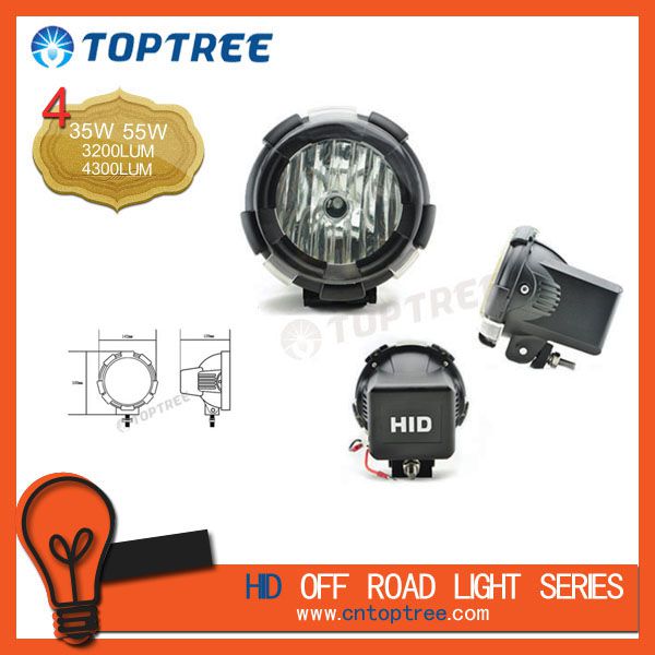
Features:
- Compact ballast is incorporated into lamp housing for easy installation – no need to mount a separate ballast
- Pre-assembled wiring harness with fuse, relay, and LED lighted switch or optional remote wiring (part# X320I)
- Computer designed Free Form/Multi Reflector for maximum light output and less glare
- Full Lens cover or Optional Stone Guard
- Heavy duty metal construction with weather and water resistant design
- Off-road and Rally tested
- Can be mounted upright or pendant.
Preparation:
- We recommend completely reading instructions before installing.
- Consult your local and state regulatory agency regarding the use of auxiliary lighting.
- The placement of auxiliary lighting should not restrict airflow to the radiator or block headlamps, turn signals, or parking lights.
Installation of the light:
- Disconnect the negative terminal (-) from the battery and wrap with electrical tape to prevent contact.
- Select a suitable attachment location and then mark and drill the 11 mm diameter hole for mounting.
Caution : consult your vehicle owner’s manual or manufacturer regarding the location of airbag or other sensors near the mounting location.
- Fit the additional headlamp (1) with washer (2) spring washer (3) and nut (4). (see diagram figure A-1 or A-2)
Wiring Harness Installation:
- The wiring harness is pre assembled and fully insulated and sleeved.
- Lay out wiring so that all connections (battery, relay, switch, and lights) will have more than sufficient length.
- Find a suitable location to mount the relay on the battery side of the engine compartment. Make sure the mounting location is not exposed to water spray, excessive heat, or moving parts.-
- Attach both power supply wires (red) to the positive (+) battery terminal.
- Connect the ground wire (black) to the vehicle chassis or the negative (-) battery terminal. Connect the wiring switch.
- Locate an unused grommet on the firewall, if one cannot be found drill a ½ inch with no obstructions on either side and away from moving parts and other wiring.
- Feed the switch connector through the firewall and into the vehicle interior to the switch mounting location.
- Select a suitable mounting location for the switch such as the dashboard or center console.
- Clean and dry both the mounting surface and the back of the switch and use double sided adhesive pad to secure.
- Plug the switch connector into the wiring harness and secure all loose wiring to ensure safe vehicle operation.
- Feed the auxiliary light wiring to each light with the shorter length going to the light on the battery side.
- Plug the power supply socket to each light and attach the ground wire (black) to the vehicle chasiss.
Optional low/high beam connection:
- Some states require auxiliary lighting to be connected to low/high beam wiring so that they may only be used when your headlights are on. An additional benefit is to prevent battery draining in case the headlights are accidentally left on. If you choose not to do this you may connect directly to the positive terminal and your auxiliary lights will operate ant any time using the switch.
- - Feed the single (re) wire to the positive(+) low or high beam wire and attach using the blue wire tap connector.
Turning on the testing operation:
- Remove the electrical tape from the negative (-) terminal and re-connect onto the battery.
- - Turn on ignition switch and activate the hid auxiliary light switch.